Understanding electrical systems requires familiarity with fundamental concepts. Electricity, governed by principles understood and refined through organizations like the IEEE (Institute of Electrical and Electronics Engineers), always seeks the easiest route. This path requires a closed loop, facilitating continuous electron movement. Essential tools, such as a multimeter, help technicians diagnose these paths. The safety, championed by professionals in the field, depends on correct identification of name for a complete path provided for electrical flow. Let’s explore what provides name for a complete path provided for electrical flow.
The electric circuit stands as a cornerstone of modern technology, a silent workhorse powering everything from the simplest lightbulb to the most complex supercomputers. It is the unseen network that brings electricity to life, transforming potential energy into a dynamic force that shapes our world.
The Foundation of Electrical Systems
At its core, an electric circuit is a fundamental element of all electrical systems. It’s the very essence of how we harness and utilize electricity. Without it, our devices would remain dormant, our homes unlit, and our industries at a standstill.
Consider the intricate web of power lines that crisscross our cities, the circuits within our smartphones, and the systems that drive our vehicles. Each one relies on the uninterrupted flow of electrical current within a closed loop.
The Necessity of a Complete Path
Electricity demands a complete and continuous pathway. Imagine trying to fill a bucket with holes – the water would simply leak out. Similarly, electrical current cannot flow if there is a break or interruption in the circuit.
This principle is paramount. Without a closed loop, the circuit is incomplete, and electricity remains static. It is this complete path that allows electrons to travel from a power source, through various components, and back again, enabling work to be done along the way.
Defining the Complete Electrical Circuit
This article aims to provide a clear and comprehensive understanding of the complete electrical circuit. We will explore its essential components, its various configurations, and the principles that govern its behavior.
By demystifying the concept of the complete electric circuit, we hope to empower readers with a foundational understanding of electricity and its applications. This knowledge is invaluable not only for those working in technical fields, but also for anyone seeking to navigate the increasingly electrified world around us.
Electricity demands a complete and continuous pathway. If there’s a break in that path, the flow stops. This is why understanding exactly what constitutes a complete electrical circuit is so crucial.
Defining the Electric Circuit: A Closed Loop for Electron Flow
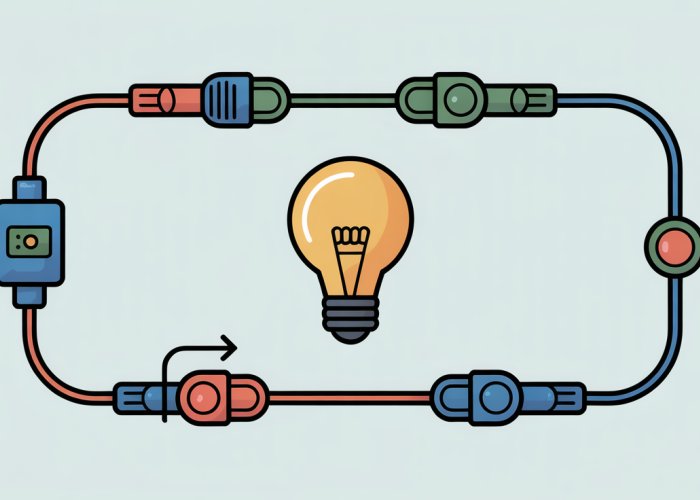
At its heart, an electric circuit is a closed loop.
This loop provides a pathway. This pathway allows electrons to flow continuously from a power source. They flow through a load. They return to the power source.
It’s a fundamental concept.
The Importance of a Closed Path
A key point to remember is this: a break anywhere in the path instantly stops the flow of electrical current.
Imagine a chain. If one link is broken, the entire chain becomes useless.
The same principle applies to an electrical circuit. Without a complete, unbroken loop, electricity simply cannot flow.
Circuit Components: Power Sources and Connections
A basic electric circuit always includes two essential elements:
- A power source.
- The wires or conductors connecting the power source to the load.
The power source provides the electrical potential energy that drives the flow of electrons.
The wires act as the pathways along which these electrons travel. Together, these components form the foundation of any functional circuit.
Electricity demands a complete and continuous pathway. If there’s a break in that path, the flow stops. This is why understanding exactly what constitutes a complete electrical circuit is so crucial.
Now, let’s move beyond the definition and explore the specific components that make an electric circuit functional. Each element plays a unique role, contributing to the overall flow and control of electrical energy.
Key Components of an Electric Circuit: Building Blocks of Electrical Flow
An electric circuit isn’t just about a loop; it’s about what makes up that loop. Specific components, each with a defined purpose, collectively enable and control the flow of electrical energy. Let’s examine these building blocks in detail.
The Role of Voltage
Voltage, often described as electrical potential difference, is the driving force behind current flow.
Think of it as the pressure that pushes electrons through the circuit.
Without voltage, there is no current, and the circuit remains inactive.
A higher voltage generally results in a greater current flow, assuming resistance remains constant.
Understanding Resistance
Resistance is the opposition to current flow within a circuit. All materials offer some resistance to electrical current.
This opposition converts electrical energy into other forms of energy, such as heat or light, depending on the component.
It’s present in various components and is a crucial factor in determining the amount of current that flows.
Switches: Controlling the Circuit
Switches are essential control elements within a circuit.
They act as gatekeepers, allowing us to open or close the circuit at will.
When a switch is open, it creates a break in the circuit, stopping the flow of current.
When closed, it completes the path, allowing current to flow freely.
This simple on/off functionality is fundamental to controlling electrical devices.
Resistors: Limiting Current Flow
Resistors are specifically designed components added to a circuit to limit current flow.
They provide a defined amount of resistance, protecting sensitive components from excessive current.
Different resistors provide varying resistance levels.
They are selected based on the specific needs of the circuit.
Resistors are vital for controlling and protecting circuits from damage due to overcurrent.
Grounding: Ensuring Electrical Safety
Grounding provides a safe path for fault current.
This means that if a short circuit or other electrical fault occurs, the current will flow to ground rather than through a person.
It is directly connected to the Earth.
This path to ground prevents electrical shocks and reduces the risk of fire. Grounding is a crucial safety measure in any electrical system.
Ohm’s Law: The Relationship Between Voltage, Current, and Resistance
Ohm’s Law is a fundamental principle that defines the relationship between voltage (V), current (I), and resistance (R): V = IR.
This law states that the current flowing through a conductor is directly proportional to the voltage and inversely proportional to the resistance.
Understanding Ohm’s Law is essential for analyzing and designing electric circuits. It allows us to predict how changes in voltage or resistance will affect the current flow.
Conductors: Facilitating Current Flow
Conductors are materials that allow electrical current to flow easily.
These are typically metals like copper and aluminum, chosen for their low resistance.
They provide the pathways along which electrons travel throughout the circuit.
The quality and size of conductors play a significant role in the efficiency of current flow.
Switches, resistors, and grounding mechanisms work together to control and safeguard electrical flow. But how does this flow behave in different arrangements?
Let’s examine how circuits can be configured and the distinct properties that emerge from each configuration.
Circuit Variations: Understanding Series, Parallel, and Short Circuits
Electric circuits aren’t uniform; they come in several arrangements, each with distinct characteristics. Understanding these variations is crucial for designing, troubleshooting, and using electrical systems safely. The three primary circuit types are series, parallel, and short circuits.
Series Circuits: A Single Path
In a series circuit, components are connected sequentially along a single path. The current flows through each component, one after the other. Think of it as a single lane highway: all traffic must follow the same route.
Characteristics of Series Circuits
-
Current is Constant: The current is the same at every point in the circuit. Because there is only one path, all electrons must flow through each component.
-
Voltage is Divided: The total voltage supplied to the circuit is divided among the components. Each component consumes a portion of the voltage, and the sum of these voltage drops equals the total voltage.
-
Total Resistance is Additive: The total resistance of a series circuit is the sum of the individual resistances. Adding more resistors increases the overall resistance.
Consequences of a Break
A key characteristic, and potential disadvantage, of a series circuit is that if the circuit breaks at any point, no current flows through any component. If one lightbulb in a series of lights burns out, the entire string goes dark. This is because the break interrupts the single path, preventing current flow.
Parallel Circuits: Multiple Paths
In contrast to series circuits, parallel circuits offer multiple paths for current to flow. Each component is connected along a separate branch, providing alternative routes for the current. This is akin to a multi-lane highway, where traffic can distribute across different lanes.
Characteristics of Parallel Circuits
-
Voltage is Constant: The voltage across each branch of a parallel circuit is the same as the source voltage. Each component receives the full voltage, irrespective of the other components.
-
Current is Divided: The total current is divided among the different branches. The amount of current flowing through each branch depends on the resistance of that branch.
-
Total Resistance Decreases: Adding more branches in parallel decreases the overall resistance of the circuit. This is because the current has more paths to flow through, reducing the total opposition.
Advantages of Parallel Configuration
Unlike series circuits, if one path breaks in a parallel circuit, current can still flow through the remaining paths. This makes parallel circuits more reliable in many applications. If one lightbulb burns out in a parallel lighting system, the others will continue to function normally.
Short Circuits: Unintended Paths
A short circuit is an abnormal condition that occurs when current finds an unintended path of very low resistance, bypassing the intended load. This often happens when insulation fails or wires come into contact with each other.
Dangers of Short Circuits
-
Excessive Current: Due to the extremely low resistance, a short circuit allows a massive amount of current to flow.
-
Heat Generation: The high current generates excessive heat, which can melt wires, damage components, and start fires.
-
Potential Hazards: Short circuits can pose significant safety hazards, including electrical shocks and burns.
Protection Measures
Protective devices like fuses and circuit breakers are designed to interrupt the current flow in the event of a short circuit. These devices detect the sudden surge in current and quickly disconnect the circuit, preventing damage and hazards.
Switches, resistors, and grounding mechanisms work together to control and safeguard electrical flow. But how does this flow behave in different arrangements?
Let’s examine how circuits can be configured and the distinct properties that emerge from each configuration.
The Flow of Current: Establishing a Continuous Path
The fundamental principle underpinning all electrical circuits is the continuous and uninterrupted flow of current. Electrical current, the movement of electrons, doesn’t just start flowing; it requires a complete pathway to transition from a state of potential energy to kinetic energy. This section will explore the essential nature of this unbroken path and the roles each component plays in facilitating it.
The Requirement for a Complete Circuit
Electrical current flows only when a continuous, closed-loop path exists. This path originates at the power source (e.g., a battery or generator), extends through the various components of the circuit, and returns to the power source, completing the loop.
Any break or interruption in this path immediately halts the flow of current.
Imagine a water pump connected to a series of pipes: the water can only circulate if the pipes form a complete, unbroken loop back to the pump. An electrical circuit operates on the same principle.
The Role of Components in Maintaining the Current Flow
Each component within an electric circuit plays a crucial role in facilitating this continuous flow. The power source provides the electrical potential difference (voltage) needed to drive the current. Conductors, typically wires made of copper or aluminum, provide a low-resistance path for the electrons to move.
Resistors, while opposing current flow, also contribute by regulating the amount of current and preventing excessive flow that could damage the circuit. Switches act as controlled breaks in the circuit, allowing us to intentionally start or stop the current flow.
Even grounding mechanisms, which provide a safe path for fault currents, play a role in ensuring the overall integrity and safety of the circuit, contributing to the potential for continuous current flow under normal operating conditions.
In essence, every component is essential for maintaining the complete and continuous flow of current. If any component fails or is removed, the circuit is broken, and the flow ceases.
Electrical circuits, with their intricate dance of voltage, current, and resistance, can seem complex at first glance. After exploring the components and configurations that make up these circuits, it’s time to test your understanding.
Test Your Knowledge: Electric Circuit Quiz
This section provides an interactive opportunity to assess your comprehension of electric circuits and their essential components. By answering the following multiple-choice questions, you can reinforce the key concepts discussed and identify areas where further review may be beneficial.
Quiz Instructions
Carefully read each question and select the answer choice that you believe is most accurate. After completing the quiz, you can review your answers to gauge your overall understanding.
Sample Questions
Here are a few examples of the types of questions you’ll encounter:
-
Which of the following is the best definition of an electric circuit?
a) A device that stores electrical energy.
b) A closed loop that provides a path for electron flow.
c) A component that resists the flow of current.
d) A measure of electrical potential difference. -
What is the purpose of a switch in an electric circuit?
a) To increase the voltage.
b) To decrease the resistance.
c) To control the flow of current by opening or closing the circuit.
d) To provide a path for fault current. -
In a series circuit, what happens if there is a break in the circuit?
a) Current continues to flow through the remaining components.
b) The voltage increases.
c) No current flows through any component.
d) The resistance decreases.
Topics Covered
The quiz will cover a range of topics related to electric circuits, including:
-
Electric Circuit: The fundamental concept of a closed-loop path.
-
Electrical Current: The flow of electrons through a circuit.
-
Voltage: The electrical potential difference that drives the current.
-
Resistance: The opposition to current flow.
-
Ohm’s Law: The relationship between voltage, current, and resistance (V = IR).
-
Series Circuits: Circuits with a single path for current flow.
-
Parallel Circuits: Circuits with multiple paths for current flow.
-
Short Circuit: An unintended path of low resistance.
-
Grounding: Providing a safe path for fault current.
-
Switches: Devices that control the flow of current.
Benefits of Taking the Quiz
-
Reinforce Learning: Solidify your understanding of key concepts.
-
Identify Knowledge Gaps: Pinpoint areas where further study is needed.
-
Improve Retention: Enhance your ability to recall and apply circuit principles.
-
Boost Confidence: Gain assurance in your understanding of electric circuits.
By actively engaging with this quiz, you can deepen your knowledge of electric circuits and enhance your ability to analyze and troubleshoot electrical systems. Good luck!
FAQs: Understanding Electrical Flow Paths
This FAQ section clarifies common questions about electrical circuits and the path electricity follows. We hope this helps you better understand the concepts discussed in our "Wiring 101" article and quiz.
What is a circuit in simple terms?
A circuit is simply the name for a complete path provided for electrical flow. It allows electricity to travel from a power source, through a component, and back to the source. Without this continuous path, electricity cannot flow.
What happens if a circuit is broken or incomplete?
If there’s a break in the circuit, like a switch being open or a wire being cut, the path for electrical flow is interrupted. This stops the flow of electricity, and the device connected to the circuit won’t function.
Why is it important that the electricity go back to its source?
The electrical source, be it a battery or outlet, needs the electrical current to complete its journey. Having a return path, or name for a complete path provided for electrical flow, is essential for energy to be delivered and perform the desired task.
What are the main components needed for a basic circuit to work?
A basic circuit needs a power source (like a battery), a conductor (like a wire) to provide the name for a complete path provided for electrical flow, and a load (like a lightbulb) that uses the electricity. All these need to be connected to create a closed loop.
Alright, sparky! Hopefully, you’re now a little bit more confident in identifying the name for a complete path provided for electrical flow. Ready to test your knowledge? Good luck with the quiz!